How to Choose an Auto Coupling Circuit?
Choosing an auto coupling circuit is not just a matter of matching two wires. The right design must carry the required signal or power while limiting noise, heat, and unwanted electrical interaction. It also needs to withstand vibration, moisture, and temperature changes inside a vehicle. Small details matter: a connector behind a dashboard faces different conditions from one near the engine bay.
The market context is changing quickly. The International Energy Agency reported nearly 14 million electric cars sold worldwide in 2023, about 18% of all new car sales (IEA, Global EV Outlook 2024). That shift brings more high-voltage systems, sensors, and control electronics into vehicles. It does not prove that every coupling circuit needs a complex design. It does mean designers should check operating voltage, current, signal frequency, isolation needs, and electromagnetic compatibility before choosing components. ISO 16750, which addresses environmental conditions and testing for road-vehicle electrical and electronic equipment, offers a useful reference for assessing vehicle-specific stresses.
Terminology can be confusing. “Coupling Circuit Auto” may describe different circuit functions across product listings and engineering teams. So, verify the schematic and datasheet rather than relying on the name alone. A promising component may still fail when exposed to heat or electrical noise. That gap matters. This guide explains how to compare circuit types, check key ratings, and assess installation conditions. It also highlights trade-offs that are easy to miss during selection. One honest limitation remains: no single circuit suits every vehicle, and real testing may challenge a tidy calculation.
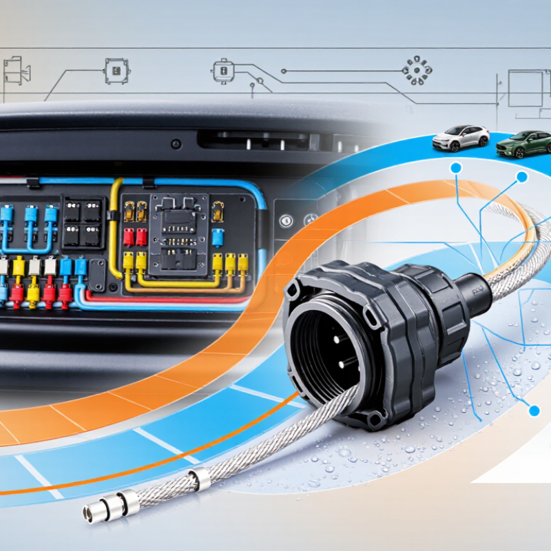
Define the Purpose and Operating Requirements of the Auto Coupling Circuit
Before choosing an auto coupling circuit, define what it must connect and what it needs to do. Is it transferring power, switching a load, or linking signals? Record the source and load voltage, peak current, signal frequency, duty cycle, and acceptable voltage drop. Also note startup surges; a circuit that works steadily may fail during a brief inrush. Set the operating temperature, vibration exposure, available space, and required service life. These details turn a vague component search into a testable specification.
Tips: Sketch the source, load, and protection path. Measure peak current under real operating conditions, not only at idle. Leave margin for heat and tolerances, then verify the circuit with a load test.
The International Energy Agency’s Global EV Outlook 2024 reports nearly 14 million electric-car sales in 2023, around 18% of global car sales. This trend highlights growing demand for dependable vehicle electrical integration, but it does not determine a circuit’s rating. Check calculations against component datasheets and test results. A tidy schematic can still miss a hot connector or a short surge. I have found that documenting assumptions helps; it also makes weak assumptions harder to hide.
Identify Voltage, Current, Signal, and Load Characteristics
Choose an auto-coupling circuit by measuring the real conditions at its terminals, not just reading the nominal supply voltage. Record minimum and maximum voltage, including switching spikes, then estimate continuous current and startup inrush. A motor or lamp can draw far more current at startup than during steady operation. Check the circuit’s thermal limits under the expected enclosure temperature, too; a rating on paper may not reflect a crowded, warm panel.
Match the signal before choosing the coupling method. Note its frequency range, amplitude, source impedance, and whether it carries noise or a DC offset. Then check the load’s impedance and required isolation. IEC 61000-4-5:2014 defines preferred surge-immunity test levels of 0.5, 1, 2, and 4 kV. These are test levels, not normal operating voltages, but they show why transient protection must suit the installation. One shortcut can mislead: matching voltage alone does not confirm safe switching or clean signal transfer.
Tips: Use an oscilloscope to inspect brief spikes, and measure inrush with a suitable current probe. Leave margin for temperature and component aging. Write down the actual load behavior; memory is a poor test instrument.
Compare Suitable Auto Coupling Circuit Configurations
When choosing an auto coupling circuit, compare how each configuration handles frequency, isolation, and signal level. Capacitive coupling passes changing signals while blocking steady DC. It suits many audio and sensor stages, but the capacitor and input resistance set a low-frequency cutoff. A small capacitor can weaken bass or slow a sensor response. Check the signal’s full frequency range before selecting its value.
Transformer coupling transfers AC energy and can provide electrical isolation or impedance matching. It is useful when those properties matter, though transformers add size and may distort signals near their operating limits. Direct coupling uses no coupling capacitor or transformer, so it can carry signals down to DC. However, bias shifts in one stage may affect the next. Noise matters. The best fit depends on real operating conditions, not just a neat schematic; I would verify it on the bench.
Tips: Compare circuit diagrams, then test the expected input range and load. Measure the output at both frequency extremes. Leave room for component tolerances; the first calculation may not match the finished circuit exactly.
Check Compatibility, Isolation, and Safety Requirements
Choose an auto coupling circuit for the actual vehicle interface, not just its schematic label. Check supply range, signal levels, peak current, switching frequency, pinout, and load behavior. Consider voltage spikes during startup and other transient conditions. Nominal voltage is not enough. Check.
The IEA’s Global EV Outlook 2024 reported nearly 14 million electric-car sales in 2023, around 18% of global new-car sales. Its Global EV Outlook 2025 projected more than 20 million sales in 2025, exceeding one-quarter of the market. These figures do not determine circuit ratings, but they highlight the need to assess mixed-voltage interfaces carefully. For galvanic isolation, verify working voltage, transient withstand, creepage, clearance, and insulation lifetime against applicable requirements, such as IEC 60664-1. Do not assume a component is suitably isolated from its label alone.
Then examine temperature range, vibration, moisture exposure, and failure behavior. Confirm that protective devices can interrupt likely fault currents, and check component derating under real operating conditions. Where applicable, assess circuit failures within the vehicle-level safety process described by ISO 26262. A neat layout can deceive. Bench-test the circuit under representative loads, then review any unexpected heating or signal distortion. Some design assumptions may still need revisiting.
Select Components and Verify Circuit Performance
An auto coupling circuit should be selected around its signal band, source impedance, and load—not just the capacitor value. For a simple RC coupling stage, estimate the low-frequency cutoff with fc = 1/(2πReqC). Choose a cutoff below the lowest wanted signal, then check the capacitor’s tolerance and leakage. A large capacitance can lower the cutoff, but it may also increase start-up delay. Small details matter.
Check component ratings against the vehicle’s operating environment. The Automotive Electronics Council’s AEC-Q100 qualification standard defines Grade 1 operation from -40°C to +125°C for integrated circuits. That range is a useful reference when choosing active components, but it does not replace checking each component’s own data sheet. Verify voltage, temperature, and transient limits for capacitors, resistors, and protection devices too. Leave margin where practical. The right amount depends on the circuit.
Verify the assembled circuit across its intended frequency range, not at one convenient test point. Measure gain, phase, noise, and settling time with the real source and load connected. Sweep slowly near the expected cutoff; a trace can reveal a misplaced pole or unexpected loading. Then repeat at temperature and supply-voltage extremes. Measure both ends. One caveat: a clean bench result may not predict every installation, so document the test setup and any remaining uncertainty.